Install and Connect WLED
WLED is an extremely awesome open source project that gives you a ton of power in a simply device like the ESP32, ESP 8266, ESP D1 Mini, or more generically the ESP-Home device collection. If you've never used one of these devices, they are absolutely incredible for DIY. They cost about $ 3.00 US each, and are currently readily available in packs of 3, 5, 6, and more. Additionally, you can do a lot with just a single board. One ESP32 device can control multiple sets of Light with WLED, and can synchronize different LED sets for a singular feel.
What You'll Need
- an ESP Home board (I use ESP 8266 boards, and here's a non-affiliate link on Amazon US
- Wago Clips (optional, but useful) - Here's a non-affiliate link on Amazon US
- LED Strip - Here's a 5 Meter Strip with a nice density of 60 LEDs / meter - Non-Affiliate LInk on Amazon US
- 5 Volt Power supply with barrel connector - Non-Affiliate Link on Amazon US
- Wire Cutter / Stripper combo tool (optional - but very handy) - Non-affiliate link on Amazon US
- Female to Female Breadboard Jumper Wires (Optional, but again, super handy) - Non-affiliate link on Amazon US
- 18 Gauge Wrie (optional, but useful as well) - Non-affiliate link on Amazon US
Now, if you look at the total for everything above, you'll be thinking "Holy Cow" that's a lot o fmoney. If you try to buy everything all at once, it could be. But notice the items I listed as optional. This is because you can often find suitable parts in your home already, if you'll just scrounge around a bit.
- For the Wago Clips, just twist wires and use some tape to keep them from touching other wires.
- For the 5 Volt power supply, if you, like many others have an old phone charger laying around (particularly with a micro USB end on it) you can use that to get started.
- Wire Cutter / Stripper (you can just use some scissors, and a bit of care)
- For the Jumper wire and / or 18 Gauge wire, you likely have some old micro USB cables lying around. Just take one, and carefully gut and strip the outer housing, and you'll find multiple suitable wiress inside that can be cut out and used.
I just knocked that initial list down to the 2 main items, LED Strip and ESP 32 board. Hopefully that helps encourage you to keep moving forward.
Also, you can find all kinds of great tutorials on Youtube on how to make a really nice light diffuser from items around your house. Hint (I made one with some parchment paper you use for cooking, and it was pretty good at about 2" distance from the lights.
Installing WLED on an ESP Device
First, plug a USB -> micro-USB cable into your computer, and plug the micro-USB end into the ESP device. Next, visit https://install.wled.me/ in a chromium based (Chromium, Google Chrome, etc) web browser (and yes, it does unfortunately need to be Chromium based, as this has the capabilities to talk to the device).
From the drop-down on the page, select the latest available version, then click the 'Install' button. You'll be prompted in a pop-up window (so make sure pop-ups are allowed for a few minutes) to select the connection where you ESP device is connected. This is usually a long string of characters in a list of fairly short options. Mine is almost always the last option on the list. When you've selected the device connection option, click the 'Connect' button.
When prompted, select 'Install WLED', then confirm the installation. You should see a ring being filled by percentage as the installation progresses. When complete, you'll see an 'Installation Successful' message on the screen. Additionally, on the ESP you may see a blue or colorful LED light up on the ESP board itself.
Click 'Next' on the success screen, and you'll be given the opportunity to configure wifi on your device. This is a good opportunity to do this so you can more easily connect to your device over the network and control your lights through a web browser or the mobile application. Select your SSID and enter the password for your Wifi when prompted, and allow the ESP device to connect.
Once connected, you'll see several options, and you can choose 'Visit Device', and you'll be taken right to the device web page / application.
That's it for installation. You are ready to start using WLED.
Configuring WLED
While WLED is really ready to run as-is, there are some settings that are important to look through. You can select the 'Config' option in the top bar of the browser, or in the bottom tabs on the mobile app. Here you'll find a list of configurations you can change. This includes setting up the Wifi in case you missed the opportunity originally.
One of the settings you'll want to set is under Config > LED Preferences. Here you'll find a set of preferences that include the data pin (I use D4, but for some reason it only responds if I set the GPIO pin to '2'). Additionally, you can set the number of LEDs you are controlling at this point. You can cut the LED strips at certain places, and thus may be controlling far less than 300 at any given time. It's wise to set this number, as it helps the board determine the proper amount of current and voltage to use for the strip, and it helps the animations work much better.
Another setting that can help is the RGB dropdown. You may need to change the order to BRG, or GRB, ,etc. This will just depend on the LED strip you purchase. Sometimes the LEDs are controlled in a different order, and this allows you to adjust that order. A good indicator that this setting may need to be tweaked is your LEDs don't appear in the color you select.
You can tweak other settings here as well, such as the default brightness. While it may be tempting to use full brightness, you'll find that 1/2 brightness (128) or less can often be more than enought for a really great, highly visible, but less distracting display.
Put your Strip Together with your ESP Device
For some folks just starting out, wiring up these items can feel a bit overwhelming, and even for me it was just confusing initially. I want to give you some details that i felt was missing when I got started. I hope this will help you understand better.
What is an "addressable" LED?
This really means that it can be addressed (like you are addressing a certain person in a group. It means you can tell this specific LED (Pixel as they are sometimes called, or Node as well), to be a certain color, or brightness, or off, or blinking, or fading, and on, and on. This is what makes these LEDs so great for amazing, interesting displays.
Wires on the Strip
The LED Strip wires (and most RGB LED Addressable LED wires) are colored in a way to let you know what they do. For an addressable LED you need at least 3 wires.
- Red - this is your power wire, or Voltage In (V In) wire. Depending on the strip you buy, this may need 5 (five) volts, or 12 (twelve) volts.
- White - This is your ground wire. In electricity, the ground is important as it allows electricity to flow. So the red (power wire sends in voltage (and current), and the white wire is where that voltage flows to. Think of it like a waterway for electricity. The water starts in at the red wire, and as it flows, it finds openings through the LED (like a drain in your sink), and the water then flows out through the drain pipe (the white - ground - wire). Electricity is much like water in a few ways. It's always wanting to take the easiest and fastest route. It is deceptively powerful, and it can be dangerous, so be careful when using electricity.
- Green - The green wire is your "data" wire. This is the wire where the board or "controller" sends the signal to each LED to tell it what it should be doing. Should it be on, off, blue, purple, white, blinking, fading, and so on. The data wire is what really gives you the power to address each LED into a certain state.
Pins on the ESP Board
The Pins on the ESP board give you the ability to wire up what you need in order for it to run the LED strip using the WLED software. If you've gotten a decent ESP board, it should have labels on the board for each Pin (GPIO). Where the pins fall on the board depend greatly on the board type. the D1 Mini GPIO is different from the ESP 8266, and that's different from the ESP32. You can easily find diagrams online for any of these boards to help you know for sure which pins do what as well.
That said, you can use the GPIO pins for the V-in (red) and GND (white) to make the board power up. You can also use the midro-USB port to get the board to power up as well, and this may be easier for you.
Powering Your LED Strip
For the LED Strip, you'll probably want to use a proper 5 V power supply for the best result, but you can use an old smart phone or table power supply as well. Good news is a lot of those have a micro-USB already. To run the LED strip, you'll need to cut the micro-USB off of the end, and strip back the outer casing. Then find your power (usually red) and ground (sometimes black, sometimes white) wires. You can use those to make the LED strip power up.
Connecting Everything
Since there are so many ways that you can wire up such a setup, I'll put a couple of diagrams below to try and help you get these wired up properly.
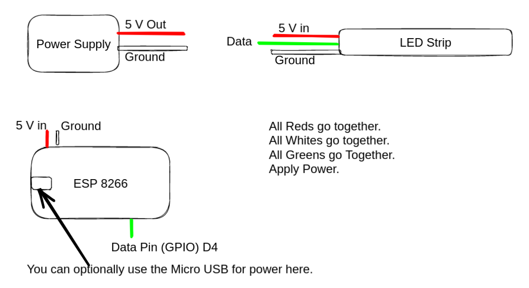
In the crude drawing above, you'll notice that I have setup red as the 5 V out / in, white as the ground, and green as the data wire. Given these things as they are, you simply connect all red together, all white together, and the green together, then plug in the power supply. This should turn on your ESP home and your LED Strip, and allow you to start sending signals to your LEDs.
Note: the Power supply is marked at "5 V Out" because it is the source of the power used to power up the other two devices which are marked as "5 V In".
I hope this will help you on your journey to lighting your life, your home, your neighborhood, and your world!
I'll be covering some more advanced lighting solutions, open source of course, later on. We are approaching Christmas, and honestly that's a huge time of year for lighting up the world.
Support My Channel
Support my Channel and ongoing efforts through Patreon:
https://www.patreon.com/bePatron?u=234177
No comments to display
No comments to display