Setup a Router / Firewall with VLANs in OpenWRT
Introduction to this Project
A brief note about this setup.: This setup is for a more complex layout with a home of about 3000 sq fet (280 sq m) in size, along with an outside (disconnected) office of 180 sq ft (17 sq m) in size, approximately 30 ft (10 m) from the closest wifi hotspot on the main house.
The outside office has been wired for connectivity by running a cable through a barried conduit. Your use case may be much more simple for a home, and you may only need the section labeled Setup Master Router / Firewall below.
If, however you are setting up a larger home where it makes sense to have multiple access points, or you are setting up a business for wired and wireless connectivity with VLANs, then the entire article will hopefully help you out.
Setup Main Router / Firewall
Initial Router Setup
Download OpenWRT for X86 Hardware Here
- Install OpenWRT on the device you want to act as your main router / firewall appliance.
- Connect one of the LAN ports on your appliance to your computer via an ethernet cable, and open your browser.
- Navigate to http://192.168.1.1 (the default page of the OpenWRT router. This is a web user interface that runs on top of the underlying linux based OS and tooling. The underlying tooling is call UCI (unified configuration interface), and the graphical user interface (or WebUI) is known as LUCI (the ‘L’ in LUCI is because the interface is programmed using the LUA programming language).
- The default login username is ‘admin’. There is no password on a fresh install or fully reset OpenWRT installation. So, simply click the Login button without any password to login.
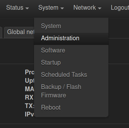
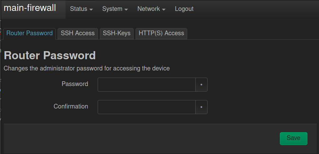
- You'll first want to set a strong password for the system, so navigate to ‘System > Administration' in the top menu, and you'll be presented with two password fields. Enter your desired password, then confirm the password, and save your changes. After saving the new password, you'll use that to login to the interface.
6. Now, there are a few other simple settings you may want to change.
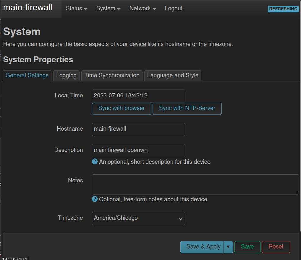
a. The name of the device can be changed under ‘System > System’ in the hostname field, from the default ‘OpenWRT’ to any name you like. I named mine ‘Main Firewall’.
b. In the same location, you can adjust the timezone to your preferred timezone as well.
c. Click ‘Save and Apply’ and wait as the changes are set in the system.
Device Setup
For the next parts, you'll need to be familiar with how to setup a static IPv4 address on your computer or device being used to connect to the OpenWRT appliance. As we make certain changes, it will be beneficial to have a statically set IP initially, and we can check DHCP settings after we have made the changes.
What are VLANs Really?
One other item to start wrapping your head around is with what VLANs really represent in OpenWRT (and even in DD-WRT for that matter). I had a hard time with this initially, but videos and guides from OneMarcFifty and DevOdyssey have really helped me with this, but it was never stated outright, so I'll state it here.
You must realize that even the LAN network (192.168.1.1) is actually just a VLAN that is defaulted on your system. It is simply not called VLAN in the user interface anywhere.
What Are We Building?
That said, we are going to create our own VLANs, and stop using the default “LAN” VLAN. We will define one of our VLANs to be our preferred (main) “LAN” network. I will be defining 4 VLANs for this article, but you can define more or less than that if you prefer. The concepts should be the same.
4 Networks:
- VLAN 10 - Default LAN - Defined with IPv4 Address of 192.168.10.1/24
- VLAN 20 - Media VLAN - Defined with IPv4 Address of 192.168.20.1/24
- VLAN 30 - Work VLAN - Defined with IPv4 Address of 192.168.30.1/24
- VLAN 40 - Guest VLAN - Defined with IPv4 Address of 192.168.40.1/24
You don't have to use the same subnet as the VLAN ID you create, but for me it makes it easier to keep track of the VLANs I'm creating, as well as what to expect for an IP as I create my network, and connect devices.
For each of the VLANs we will also create a Wireless Network (SSID) to go along with it.
Setup our First VLAN
In the OpenWRT LUCI interface, navigate to “Network > Interfaces”. Here, you may see only 1 interface, or you may see several interfaces. What you see will depend on your hardware to some extent. In my case I'm setting up an X86 device with OpenWRT, so I initially only see one interface called “LAN” and it is only inclusive of one of the five available ethernet ports on the device.
The LAN is setup as a bridge (this just means that ports are being tied together in software to perform the same, or similar actions). A bridge in a device like this will usually have four ports tied together, with a single port left separate that is used as the WAN port (or the internet modem connection). So, let's go add the other 3 ports to our default bridge. In my case this bridge is called “br-lan”. On the “Interfaces” view, go to the “Devices” tab, and take note of the various devices that may be listed. We are looking for the br-lan device. If you don't have any bridges listed, it's okay. We can create one easily.
Create a Bridge
You should only do this if you don't already have a bridge device listed. If you do already have one, skip down to the “Edit Our Existing Bridge” section. To create a bridge do the following:
- Click the “Add Device Configuration” button on the “Devices” tab.
- Choose a ‘Device Type’ of ‘Bridge Device’ from the drop-down menu.
- Give your new device a name. You can name it anything you want, but the standard is to call it “br-lan”.
- Select the interfaces you want to bridge from the drop-down by click on them to check the box. You can de-select any interfaces you don't want included by click on them again to remove the check. In my case I selected eth1, eth2, eth3, and eth4.
- Check the box that says “Bring up empty bridge”.
- Click ‘Save’ at the bottom of the screen.
Edit Our Existing Bridge
If you already have a bridge device defined, click the ‘Configure’ button to the right of the bridge name.
- On the General Device Configuration tab, choose the interfaces you want to bridge together as part of your “lan” interface. You don't have to bridge all ports, or even more than 1 port, but in my case I tied all four of my ports together by selecting eth1, eth2, eth3, and eth4.
-
Check the box next to “Bring up empty bridge”.
-
Click ‘Save’ at the bottom.
Add VLANs
A couple of terms that will help you (I hope) as we move forward with the next part of our setup:
- VLAN Trunk or Trunk Port - This is the term used for a port or cable that is assigned multiple tagged VLAN IDs.
- Tagged VLAN - Tagged refers to a defined VLAN ID that is to be passed along to other devices from a specified port.
- VLAN Aware - a device that can receive and interpret VLAN IDs (VLAN Tags) (e.g. Managed Switch, Router, Wireless Router, Access Point, etc).
- Untagged VLAN - For devices that are not “VLAN Aware”, the VLAN ID (or VLAN Tag) is ignored, or simply not seen. In order for those devices to still be able to connect, we need to define a port or line (cable) that will carry traffic which can be read by these devices (e.g. Computer, Laptop, Tablet, Phone, etc).
- In the Devices tab, click ‘Configure’ next to our br-lan device.
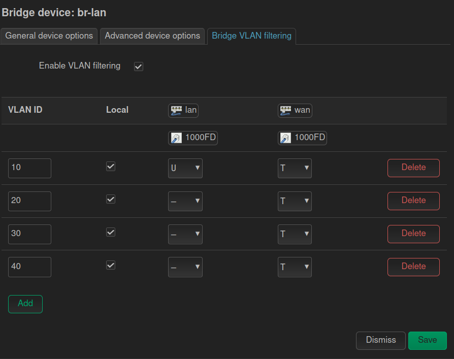
- Move to the ‘Bridge VLAN Filtering’ tab.
- Click the ‘Add’ button for as many VLANs as you want to create. (Remember we are creating a VLAN to act as our main “LAN” or Local Area Network, ,as well as a few extra VLANs for other segmentation of devices on our network).
- I added four VLANs. On each VLAN you add, set the VLAN ID (tag) you want for each. They likely defaulted to 1, 2, 3, and 4 if you added four VLANs as well.
- I changed my VLAN IDs (Tags) to 10, 20, 30, and 40.
- Click ‘Save’, but do not click ‘Save and Apply’ yet.
- Navigate back to the Devices tab, and click Configure for br-lan again. Now, on the “Bridge VLAN Filtering” tab, we want to start assigning the VLANs to our various bridged physical interfaces.
The good news is, you can make a lot of changes in OpenWRT, but none of them will take full effect until you click ‘Save and Apply’. This allows you the opportunity to get the system into your
NOTE: It is not required to assign a VLAN to a physical port, though in our setup we will need to assign our default VLAN to one port in order to keep access to the router / AP. This may be the case if you are only setting up VLANs for wireless access.
First, let's choose one of our ports to be our VLAN Trunk (the port that will pass all of the VLAN IDs to the rest of our network). In my case, I selected eth4, but on my APs I have fewer ports, so I'll use one of the ports on those as the VLAN Trunk as well.
Next, we need to set the VLAN we want to use as our main LAN network to “untagged” on one of the other ports. My suggestion is to set this on the port you are currently connected to. Leave the other VLANs set to “Not Participating” or “Not Member” on that port.
What are we doing here?
We are setting up our router to send out the VLAN traffic on a specified port (the VLAN Trunk) so that our Access Points and Managed Switches down the line can pick up that VLAN traffic and put it to use. We are also setting one port aside for us to connect a computer to, and ensure we can still get an IP from our main LAN (VLAN 10 in this case) network. This helps make sure we don't get locked out of our Router.
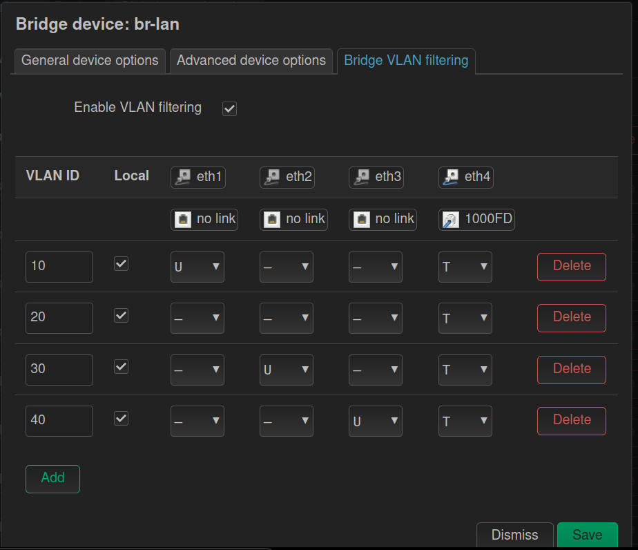
Since I had two more ports, I went ahead and marked eth2 as untagged for VLAN 30 (which will allow me to connect to port 2 on my device, and get an IP address in the 192.168.30.x range (once I've setup my interface and DHCP, of course). Additionally, I setup eth3 for VLAN 40 for the same reason.
Once you've setup your system in a similar manner, click ‘Save’.
Before we apply all of these changes, we need to do a couple of more things.
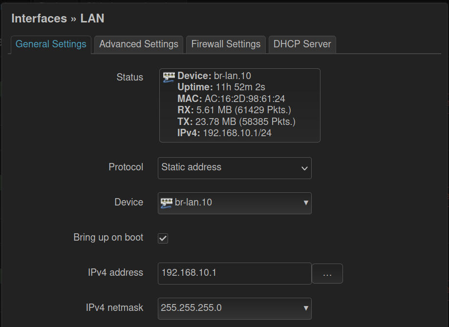
- Under ‘Networking > Interfaces’ on the Interfaces tab, we need to change the ‘lan’ interface to use a different bridge device (our main lan VLAN).
- Click on ‘Edit’ to the right of the br-lan interface, and in the
- Use the ‘Device’ drop-down list to select our main LAN VLAN id. It should say something like "br-lan.10".
- Change the IPv4 Address to be whatever IP address you want this main router to be. In my case I set it to match my VLAN ID (Tag) at 192.168.10.1
- Next, select the netmask from the IPv4 Netmask field: normally this will be the option of “255.255.255.0”
- If you want to expand or decrease the number of DHCP addresses that can be handed out for this VLAN, click the ‘DHCP Server’ tab, and adjust the ‘Start’ and ‘Limit’ values. In my case, this will be my main LAN, so I set it from Start = 10, to Limit = 220.
- Click ‘Save’.
Almost there! Now we'll create three more interfaces. Enough for each VLAN to have 1 (one) interface.
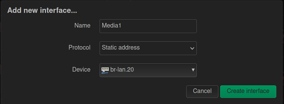
- On the Interfaces tab, click ‘Add New Interface’
- On the window that pops-up, give your new interface a meaningful Name. I called my VLAN 20 Interface “Media”, as it will be used for my media devices like Roku, Apple TV, etc.
- Select ‘Sttaic Address’ for the Protocol field.
- Select your second VLAN as the Device. In my case it was "br-lan.20".
- Click ‘Create Interface’.
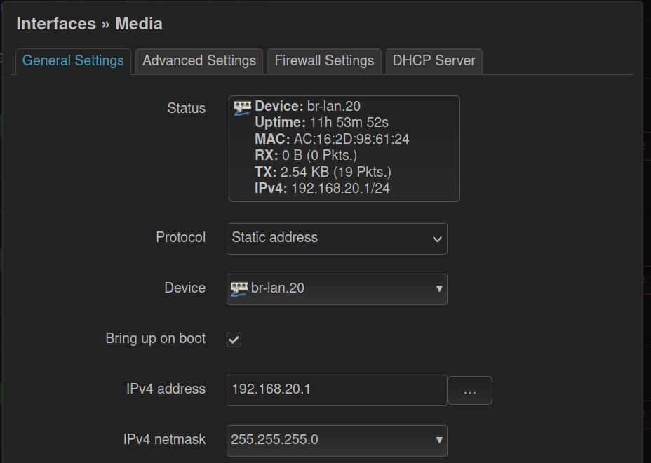
Next, you'll be taken to the same screen as you saw when Editing the lan interface.
- Enter the IPv4 Address for this VLAN. I used 192.168.20.1 as this is VLAN 20.
- Enter the neetmask (select it). I selected 255.255.255.0.
- Move to the ‘Firewall Settings’ tab.
- Click the drop-down and select the same zone as LAN. You'll see each interface added here as you add each new Interface to this zone.
- Move to the DHCP Server tab and click the button “Setup DHCP Server”.
- Again, adjust the DHCP range limit if you wish to, otherwise the default range of 100 to 200 will be used.
- Click ‘Save’
Repeat the above steps for as many VLANs as you are creating. You should have 1 interface for each DHCP server.
Now, we are getting ready to click ‘Save and Apply’. When you do you'll be warned that if you make this change the address you are accessing the LUCI web interface on will change, and you'll need to manually move to the new address.
- Click ‘Save and Apply’
- Click the Red button to ‘Apply the Changes’
Now you need to quickly adjust your computer's network adapter to have a static address in the new main LAN VLAN range, or you need to re-enable DHCP so it will pull a new address. If your changes are successful, you should get a new address in the main LAN (VLAN) IP range from the DHCP server. In my case I was given 192.168.10.125, so I knew I was connected.
After getting a new IP, you need to head back to your LUCI web interface to ensure it's still reachable. You'll use the static IP you set on the VLAN subnet for the interface. In my case I went to 192.168.10.1 and was immediately able to login and view all of my Interfaces.
Pitstop - Check In
If you are just setting up one device, then it's time to create your wireless networks from your VLANs and see if you can connect successfully.
Creating a Wireless Network for a VLAN
The great thing about VLANs in most systems, but especially in OpenWRT and DD-WRT is you can setup different Wireless Networks (SSIDs) for each VLAN. This helps with keeping your wireless IoT devices segregated from the rest of your network, or for providing Guest access at your home, or in an office, but making sure those unknown / untrusted guest devices can't reach the devices on your main VLANs.
In the LUCI interface we are going to move to the ‘Interfaces > Wireless’ page. Assuming you have a wifi raidio / card in your router that is capable of being an access point (AP), you'll see anywhere from 1, 2, 3, or maybe even 4 “Radios”. The “Radio” represents the physical device that can transmit and receive wirelss (wifi) signals. Each Radio can be setup with one, or several, wifi networks (SSIDs), each of which can have their own security settings, and each be setup to utilize a specific VLAN as its network backbone.
You may see a few wireless networks already in place by default. Most likely these will be labeled OpenWRT, and they have no security set on them yet. You can either Edit those using the instructions below (aside from the ‘Add’ step), or you can remove those networks, and add new ones for each radio available to you. For this tutorial, we'll remove the existing ones, and add new ones, but editing an existing one is also a perfectly fine route.
Remove Existing Wifi Networks
- Under each Radio entry, you'll see any wireless networks setup for that radio. Simply click the ‘Remove’ button to the right of the wireless networks.
- After removing all existing wireless networks, click ‘Save and Apply’.
WARNING! If you are connecting to your device through Wifi, and not through an ethernet wire, you should not do the above! You will lose access to the device. You must either edit your current Wifi SSID / Network, then reconnect to it after 'Save adn Apply', or you must first connect with a wire.
Add New Wifi Networks
The different Radios on a router / appliance are generally able to broadcast on different frequency ranges, and carry different types of wifi signals. 802.11 a, b, g, and n are generally broadcast on the 2.4 GHz bands, while 802.11 n and ac are broadcast in the 5 GH band. You also now have 802.11 ax (Wifi 5 and 6) that can broadcast in the 6 GHz frequency band. This just means you may have a few radios with differing capabilities.
| Wifi Type | Frequency / Band | Speed / Distance |
| 802.11 a b g and n | 2.4 GHz | Slowest / Longest |
| 802.11 n and ac | 5 GH | Faster / Shorter |
| 802.11 ax | 6 GHz | Fastest / Shortest |
- Next to the radio of your choice, click the ‘Add’ button.
- Depending on the Radio's capability you will see optionsin the drop-down called Operating Frequency. You'll usually want to set this to be N only, or AC Only depending on the frequency, but there are cases where a mixed mode (BGN or acn) may be desirable. Generally, OpenWRT will auto select the fastest option, so unless you have a reason to set mixed mode, I suggest just settingit to N or AC / AX only.
- Moving down the window, you'll want to change the ESSID to be something more meaningful to you, and easily identifiable for you if you live in an area with a lot of wifi signals.
- Now select the Network you want this Wireless option associated with. You can select any of the VLANs you created. For instance, if I was creating my Media wifi, I'd name it MacG-Media, and select my “Media” interface from the list.
- Move to the Wireless Security tab, from the drop-down select a Security mode (usually WPA2 or WPA3 are your best options.
- Set your security password and enter it in the “Key” field.
- (OPTIONAL) If you are setting up multiple access points (APs0, you'll likely want to move to the WLAN Roaming tab, and check the box for 802.11r Fast Roaming to enable it.
- Once enabled move down to the “Mobility Domain” field and set a four character code of your choice. Valid options for each character are 0 - 9 and a - f only. You might set the Media network code to 112c. You will then set this same Mobility domain code on each wifi AP you setup for the Media wireless network, so as you move around the property, your devices will auto-move to the closest AP / strongest signal.
- Click ‘Save'.
You can now click ‘Save and Apply’, or you can create other networks for the same radio, or for the other Radios. There are 100s of ways you could setup your wifi system, so I'll leave that to you, but you now have the tools to get hsoe wifi networks added and associated to the VLAN interfaces you've made.
The next section is part of part 2 in this video series. This is where we'll setup separate Access Points (APs) that do not do any routing, DNS, Firewall, or DHCP assignment, but instead rely on the Main Router (setup above) to handle all of those details.
Setup APs with VLANs
This next section is for those of you who are setting up multiple devices. The router, which we did above, and additional Access Points (APs). These APs maybe wired only, wireless, or a combination depending on your needs and your hardware capability.
Essentially, we'll do almost the exact same steps as we did for the router, except that we need to turn off / disable DHCP on these AP only devices, and we want to set their static IPs for each VLAN to be different from that of the main router, and different from all of the other APs.
Planning
It is always best to plan out a more complex network setup. Think through where these APs will be, where you main incoming internet connection lives, where you'll need cables run, and where the optimum positions for your Wifi APs may be based on your property layout.
That said, one of the core planning items you can do is to make a simple table that lists your physical devices (APs) and what you want their IP addresses to be for Each VLAN.
| Device | VLAN 10 (lan) | VLAN 20 (Media) | VLAN 30 (Work) | VLAN 40 (Guest) |
|---|---|---|---|---|
| Main Router | 192.168.10.1 | 192.168.20.1 | 192.168.30.1 | 192.168.40.1 |
| AP-1 | 192.168.10.2 | 192.168.20.2 | 192.168.30.2 | 192.168.40.2 |
| AP-2 | 192.168.10.3 | 192.168.20.3 | 192.168.30.3 | 192.168.40.3 |
| Ap-3 | 192.168.10.4 | 192.168.20.4 | 192.168.30.4 | 192.168.40.4 |
You can add columns to the table above to list physical locations for each device, whether the device has wireless networks for each VLAN, or only wired, and on which ports each VLAN is set, and so on. As your network grows, this can be a very useful tool. IF you are getting much beyond what I have here, you may want to look into some software like Netbox, or something similar to layout and keep track of your network.
Setup our First AP Only Device
Initial Router Setup
- Install OpenWRT on the device you want to act as your main router / firewall appliance.
- Connect one of the LAN ports on your appliance to your computer via an ethernet cable, and open your browser.
- Navigate to http://192.168.1.1 (the default page of the OpenWRT router. This is a web user interface that runs on top of the underlying linux based OS and tooling. The underlying tooling is call UCI (unified configuration interface), and the graphical user interface (or WebUI) is known as LUCI (the ‘L’ in LUCI is because the interface is programmed using the LUA programming language).
- The default login username is ‘admin’. There is no password on a fresh install or fully reset OpenWRT installation. So, simply click the Login button without any password to login.
- You'll first want to set a strong password for the system, so navigate to ‘System > Administration' in the top menu, and you'll be presented with two password fields. Enter your desired password, then confirm the password, and save your changes. After saving the new password, you'll use that to login to the interface.
- Now, there are a few other simple settings you may want to change.
- The name of the device can be changed under ‘System > System’ in the hostname field, from the default ‘OpenWRT’ to any name you like. I named mine ‘Main Firewall’.
- In the same location, you can adjust the timezone to your preferred timezone as well.
- Click ‘Save and Apply’ and wait as the changes are set in the system.
Create a Bridge
You should only do this if you don't already have a bridge device listed. If you do already have one, skip down to the “Edit Our Existing Bridge” section. To create a bridge do the following:
- Click the “Add Device Configuration” button on the “Devices” tab.
- Choose a ‘Device Type’ of ‘Bridge Device’ from the drop-down menu.
- Give your new device a name. You can name it anything you want, but the standard is to call it “br-lan”.
- Select the interfaces you want to bridge from the drop-down by click on them to check the box. You can de-select any interfaces you don't want included by click on them again to remove the check. In my case I selected eth1, eth2, eth3, and eth4.
- Check the box that says “Bring up empty bridge”.
- Click ‘Save’ at the bottom of the screen. Do not click 'Save and Apply' yet.
Edit Our Existing Bridge
- If you already have a bridge device defined, click the ‘Configure’ button to the right of the bridge name.
- On the General Device Configuration tab, choose the interfaces you want to bridge together as part of your “lan” interface. You don't have to bridge all ports, or even more than 1 port, but in my case I tied both of my ports together by selecting eth1 and eth2 (actually listed as 'lan' and 'wan' on this device).
- Check the box next to “Bring up empty bridge”.
- Click ‘Save’ at the bottom.
Add VLANs
- In the Devices tab, click ‘Configure’ next to our br-lan device.
- Move to the ‘Bridge VLAN Filtering’ tab.
- Click the ‘Add’ button for as many VLANs as you want to create. (Remember we are creating a VLAN to act as our main “LAN” or Local Area Network, ,as well as a few extra VLANs for other segmentation of devices on our network). Since this is for an AP we want the number of VLANs to match what we made for the main router.
- I added four VLANs. On each VLAN you add, set the VLAN ID (tag) you want for each. They likely defaulted to 1, 2, 3, and 4 if you added four VLANs as well.
- I changed my VLAN IDs (Tags) to match those I made for the Main Router - 10, 20, 30, and 40.
- Click ‘Save’, but do not click ‘Save and Apply’ yet.
- Navigate back to the Devices tab, and click Configure for br-lan again. Now, on the “Bridge VLAN Filtering” tab, we want to start assigning the VLANs to our various bridged physical interfaces (the actual ports on the device).
- First, let's choose one of our ports to be our VLAN Trunk (the port that will pass all of the VLAN IDs to the rest of our network). In my case, I selected eth2 (wan).
- Next, we need to set the VLAN we want to use as our main LAN network to “untagged” on one of the other ports. My suggestion is to set this on the port you are currently connected to. Leave the other VLANs set to “Not Participating” or “Not Member” on that port.
NOTE: It is not required to assign a VLAN to a physical port, though in our setup we will need to assign our default VLAN to one port in order to keep access to the router / AP. This may be the case if you are only setting up VLANs for wireless access.
What are we doing here?
We are setting up our AP to receive the VLAN traffic on a specified port (the VLAN Trunk) so that our Access Point can pick up that VLAN traffic and put it to use. We are also setting one port aside for us to connect a computer to, and ensure we can still get an IP from our main LAN (VLAN) network. This helps make sure we don't get locked out of our AP.
Once you've setup your system in a similar manner, click ‘Save’.
Before we apply all of these changes, we need to do a couple of more things.
- Under ‘Networking > Interfaces’ on the Interfaces tab, we need to change the ‘lan’ interface to use a different bridge device (our main lan VLAN).
- Click on ‘Edit’ to the right of the br-lan interface, and in the
- Use the ‘Device’ drop-down list to select our main LAN VLAN id. It should say something like "br-lan.10".
- Change the IPv4 Address to be whatever IP address you want this AP to be. In my case I set it to match my VLAN ID (Tag) at 192.168.10.2 (one higher than my main router).
- Next, select the netmask from the IPv4 Netmask field: normally this will be the option of “255.255.255.0”
- On the ‘Advanced Settings’ tab I set the main router IPv4 address as the only DNS entry.
- On the Firewall tab I left this interface in the ‘lan’ zone. I don't belive the AP needs to have anything in the 'lan' zone, so you can set this to 'unspecified' if you prefer.
- On the DHCP tab, we need to check the box that says ‘Ignore this interface’.
- Click 'Save'.
Add the Other VLAN Interfaces
Just like we did on the main router, we need to add the other VLANs as interfaces on this AP. The only difference is the Firewall nad DHCP setup, as seen in the steps below.
- On the Interfaces tab, click ‘Add New Interface’
- On the window that pops-up, give your new interface a meaningful Name. I called my VLAN 20 Interface “Media”, as it will be used for my media devices like Roku, Apple TV, etc.
- Select ‘Sttaic Address’ for the Protocol field.
- Select your second VLAN as the Device. In my case it was "br-lan.20".
- Click ‘Create Interface’.
Next, you'll be taken to the same screen as you saw when Editing the 'lan' interface.
- Enter the IPv4 Address for this VLAN. I used 192.168.20.2 as this is VLAN 20.
- Enter the neetmask (select it). I selected 255.255.255.0.
- Click ‘Save’
There is no need for the firewall zone, the DNS, or the DHCP server in this case as this will all be handled by the main router, and not this AP.
Repeat the above steps for as many VLANs as you are creating. You should have 1 interface for each DHCP server.
Now, we are getting ready to click ‘Save and Apply’. When you do you'll be warned that if you make this change the address you are accessing the LUCI web interface on will change, and you'll need to manually move to the new address.
- Click ‘Save and Apply’
- Click the Red button to ‘Apply the Changes’
You'll need to connect the two trunk VLAN ports together from the main router to the AP, then use the untagged port on the AP to connect your computer to. Again having your computer setup for DHCP, you should get an assigned address in the untagged VLAN range for the port you connect to. Sometimes it helps to unplug the Ethernet cable, wait about 10 seconds, then plug it back into your computer.
Creating a Wireless Network for your VLANs
You can simply follow the same steps for the wireless setup as we did on our main router. Make sure you set the Wifi SSID to match, and if enabling Fast Roaming that you also set the Mobility ID to match what you used on the other router / APs.
Repeat these steps as you setup each AP you have, and remember to change their static IPs on each VLAN so they are different from your other APs and Router.
Now, you're ready to setup your home or buisness with Wireless Access.
Firewall Zones and Setup in OpenWRT
OpenWRT defines it firewall rules by "zones". You create a zone, and name it whatever makes sense to you. You then set rules on that zone. There are three parts to a zone.
- Input - Traffic coming into that zone.
- Output - Traffic being sent out from that zone.
- Forward (forward has parts for forwarding traffic inside a zone between VLANs, as well as forwarding between two zones. Keep this in mind when adjusting / adding firewall zones and rules).
In our setup thus far, we have set each VLAN interface in the same zone. LAN, Media, Work, and Guest are all currently in the "LAN" zone. The naming can cause confusion, so let me take a moment to try and help you keep things straight as we go through this. The "LAN" zone is a default zone that is setup by OpenWRT "out-of-the-box". This is just a name used to emphasize that the "LAN" zone is set for the default lan interface. Think if the naming as a mapping between zone and interface. The zone does not have to be named the same as an interface.
In order to keep things a bit easier to follow in this section, I'll be naming my firewall zones with the "_FW" suffix.
| Interface |
Firewall Zone |
| LAN |
LAN_FW |
| Meida |
Media_FW |
| Work |
Work_FW |
| Guest |
Guest_FW |
Understanding the Default Firewall
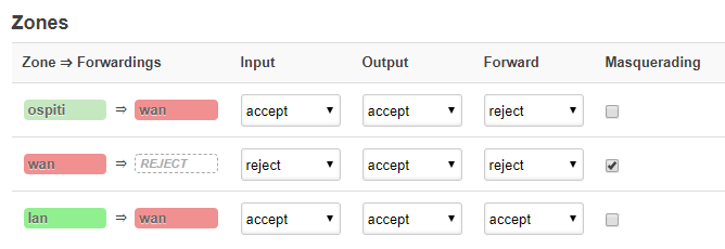
In the image above, you'll see a couple of important things. The colorful rounded rectangles represent the firewall zone, not the interface with the same name. What we see is that the lan zone has a forward rule to the wan zone (this is the forward between zones). Next, under the columns (Inpurt, Output, Forward), you'll see the 3rd line for the lan zone, shows that it will accept input (you can reach the router and UCI / LUCI interface on the lan zone), it will accept (or allow) output (traffic can travel out of the zone without being blocked), and Forward between devices inside the zone (for the most part, don't worry too much about the last column titled 'Forward'.
Next, we see on the wan zone, that it is not forwarding to any other zone (which we wouldn't want since this zone faces the internet. Additionally, it rejects input (which means the internet can't come into the wan zone...it blocks attempts to come in from the outside). Next, it accepts (allows) output, which means it can reach out to the internet to make requests (very important if you're expecting to get to the internet). Finally, the forward column is set to reject. We also see that the Masquerade checkbox is checked for the wan zone. This is what allows a machine inside our network to make an internet request, and receive back the responses to it's request essentially. Not something you need set on internal networks in most cases.
Planning VLAN Communication
What we need to think through is how do we want our VLANs to communicate? Which VLAN should be able to talk to which other VLANs? Which VLANs should have access to the internet or not? We can use a simple table to help us define how we want our firewall zones to be setup.
| VLAN Name |
VLANs it can Talk To |
Has Internet Access? |
| LAN |
LAN, Media, IoT |
Yes |
| Media |
Media |
Yes |
| Work |
Work, Media, IoT |
Yes |
| Guest |
Guest |
Yes |
| Iot |
none |
No |
You'll notice I've added a VLAN I didn't talk about creating, but it's to help exemplify what the firewall zones can do. IoT has been added as it is a more limited VLAN intentionally.
At first glance, you might think that "LAN" and "Work" look the same, so they could go into the same zone. In reality, the difference is that those two VLANs aren't being allowed to communicate with each other, so they will each need their own zone. If, however, you fill out the table, and you find more than one VLAN has the same set of VLANs they are allowed to talk to, and the rule for reaching the internet is the same for those VLANs, then they can absolutely go into the same firewall zone.
Setting up our Media VLAN in a Firewall Zone
First, let's put our Media VLAN in a firewall zone. Media is only allowed to see devices in the Media VLAN, but it does have access to the internet. If you look closely, you'll see that the Guest VLAN will be setup the same way, but because it is not allowed to see the Media VLAN, and the Media VLAN isn't allowed to communicate with the Guest VLAN, we still need to setup separate firewall zones for these VLANs.
- Click the 'Add' button at the bottom of the Firewall page.
- In the dialog that pops up, name your new firewall zone. I like to name my zone in a way that makes it easy to identify what it is doing. So for this I'll name it Media_FW.
- Set 'Input' as 'Accept'.
- Set 'Output as 'Accept'.
- Set Forward as 'Reject'.
- Leave the 'Masquerade' checkbox unchecked.
- In 'Covered Networks', select your Media VLAN.
- In the 'Allow forward to destination zones', select 'wan'.
- Click 'Save'.
Note: You can also set the 'Covered Networks' by going to Interfaces > Interface, then clicking Edit for the interface you want to set a firewall zone for, and selecting your newly created firewall zone. Just a second way to accomplish the same result of setting a firewall zone on an interface.
You can now click 'Save and Apply'. Once you are back in the LUCI interface, you may want to connect a device to the Media interface, and run some tests to ensure the firewall rule is working as desired.
Tests You Can Run
| Test |
Expected Result |
| Ping test between two devices on the Media VLAN | Should succeed |
| Ping test from Media VLAN to another VLAN |
Should fail |
| Bring up sites on the internet. |
Should succeed |
Setup our IoT Firewall Zone
When we look at our Iot VLAN / Firewall Zone, we see that we don't want the IoT VLAN to have internet access, and we don't want the IoT VLAN to be able to communicate out to any of our other VLANs, but we do want some of our other VLANs to be able to reach our IoT VLAN.
- Click the 'Add' button at the bottom of the Firewall page.
- Give your new zone a name that helps you identify it easily. I'll call mine 'IoT_FW'.
- For 'Input' set it to Accept, as we want the IoT devices to be able to talk to the router, and in turn each other as needed.
- For 'Output' set it to Accept as well. This only allows it to send out traffic inside it's own network for now. We'll set it to keep it like this.
- For 'Forward' set it to Reject.
- For covered networks, select 'IoT'.
- In 'Forward to destination zones' leave it as 'unspecified'.
- In 'Forward from source zones', also leave it as unspecified.
- Click 'Save'.
You can now click 'Save and Apply' to apply these changes.
Run similar tests to our Media_FW zone setup.
| Test |
Expected REsult |
| Ping another device on the IoT network |
Success |
| Ping a dvice on any of the other VLANs (lan, media, work, guest) |
Fail |
| Reach the internet |
Fail |
Modify our lan_FW Zone
Recall that we want our lan network interface (VLAN) to be able to reach the Media VLAN and the IoT VLAN. You can, of course, apply this setup to any other VLANs you want the lan VLAN to reach.
- Next to the 'lan' zone settings, click the 'Edit' button tot he right
- Move down to the 'Forward to destination zones' setting, and add the Media VLAN and IoT VLAN by clicking them to check their checkboxes.
- Click 'Save'.
- Click 'Save and Apply'.
Run similar tests to those for the zones above.
| Test |
Expected Result |
| Ping another device on the 'lan' VLAN |
Success |
| Ping a device on the Guest or Work VLAN |
Fail |
| Ping a device on the Media or IoT VLAN |
Success |
| Reach the internet |
Success |
Congratulations! You have now setup a router with OpenWRT and multiple VLANs. You have likely also expanded your network's reach by adding Access Points running OpenWRT with multiple VLANs. Last, but not least, you have setup Firewall rules to help keep your network traffic more safe and secure.
An Extra for VLAN NAT Reflection (A.K.A. Hairpinning, NAT Loopback)
Now that we've setup our firewall rules, one thing I don't have is NAT Reflection on my non-LAN VLANs. So for instance if I wanted my Guest Network to be able to call a server I'm running here at my house, it won't be able to reach it. Only the devices on my main VLAN (LAN) network will be able to do this.
As of OpenWRT 23.05.2, this is still not available in the LUCI Web UI for OpenWRT. Why, I have no idea. The way to fix it however isn't super hard. You just need to add a line or two to the "firewall" configuration file in your main router.
First, SSH to your router. You may need to enable SSH in the LUCI interface under System >> Administration under the SSH Access tab. Enable the access and then Save and Apply. Now, from the terminal SSH to your box by entering:
ssh root@<your main router IP address>
In my case I did
Once logged into your router in the terminal, we need to edit our "firewall" configuration file. We'll be using the VI text editor for this, as nano is not installed (at least not by default).
vi /etc/config/firewall
Once in the config file, be careful not to press the "i" key, as this is what puts the file into "insert" (edit) mode. We want to search for a specific rule in this file, then add a few lines to the rule. In fact, we want to search for two rules, one that affects http (or traffic on port 80), and one that affects https (or traffic on port 443). To search, we'll use the slash '/' key, then type our search value.
/redirect
This should take you to a section wthat starts with
config redirect
We want to make sure this is the redirect to our lan, so make sure it looks something like this (though it may not be exactly the same).
config redirect
        option dest 'lan'
        option target 'DNAT'
        option name 'http'
        option src 'wan'
        option src_dport '80'
        option dest_ip '192.168.10.17'
        option dest_port '80'
The important parts are that it's for dest 'lan', and target 'DNAT', and src_dport '80'. Once you find this section you'll want to add a line, or maybe a few lines depending on how many VLANs you want to have hairpinning enabled. We need to add a line like this:
list reflection_zone 'lan'
To edit the file, press the 'i' key to go into insert mode. To stop editing, you can press the ESC key at any time. We need to add a line like this for each VLAN we want to give hairpinning to. My final config for port 80 ended up like this:
config redirect
        option dest 'lan'
        option target 'DNAT'
        option name 'http'
        option src 'wan'
        list reflection_zone 'lan'
        list reflection_zone 'MediaFW'
        list reflection_zone 'Work'
        option src_dport '80'
        option dest_ip '192.168.10.17'
        option dest_port '80'
Where I added the three lines for list reflection_zond 'lan', list reflection_zone 'MediaFW', and list reflection_zone 'Work' to my file so that the LAN, Work VLAN, and Media VLAN would each have hairpinning on port 80.
We are almost done. Assuming you also want hairpinning for your same zones on port 443, find the next config redirect section, and make sure it's got the line option src_dport '443', and add those same lines to it.
config redirect
        option dest 'lan'
        option target 'DNAT'
        option name 'https'
        option src 'wan'
        list reflection_zone 'lan'
        list reflection_zone 'MediaFW'
        list reflection_zone 'Work'
        option src_dport '443'
        option dest_ip '192.168.10.17'
        option dest_port '443'
Finally, you may have some other port forwards you made in the LUCI interface. If so, find their redirect sections as well, and make sure to add the appropriate VLANs you want to be able to reach those too.
When done making edits press the ESC key on the keyboard, then type :qw, then press Enter to save and exit the file.
Now reboot your router, and check that you can reach your internal servers by their public URLs from each VLAN.
Support My Channel and Content
Support my Channel and ongoing efforts through Patreon:
https://www.patreon.com/awesomeopensource
No comments to display
No comments to display